Read time 10 min
Understanding Antenna Gain: Insights for Great Wireless Performance
Antenna TestingAntennaGain
In the beginning of August I gave a presentation on #EMC2021. Event lasted whole week and gathered a lot of 5G and mm-wave enthusiasts. I was talking about my experience with mm-wave antenna arrays, starting from the idea and finalizing with real life measurements. The topic got many feedbacks, so I decided to modify it to a blog and once more explain the whole process.
So the idea was pretty basic - we wanted to create a 4x1 dual-polarized phased array for the 26-30GHz range. We want it to be cheap, compact, and easy to manufacture and test. Ideally, our goal was to create an antenna element, that is not dependent on the ground plane size of the primary device. Oh, and yes, we wanted an end-fire radiation pattern.
The first challenge comes straight from the previous statement. "Cheap" - means PCB antenna, but how to make it both: compact and with an end-fire radiation pattern? Let's call it "the antenna structure challenge".
Okay, assuming we have the ideal structure, how to simulate it correctly, taking into account manufacturing nuances and considerations? Mm-wave antenna prototyping is super complicated as it is, we don't want to have more troubles. This is "the implementation challenge".
Now, we have the structure and we figured out how to simulate it properly. What's left? Right, "the measurement challenge".
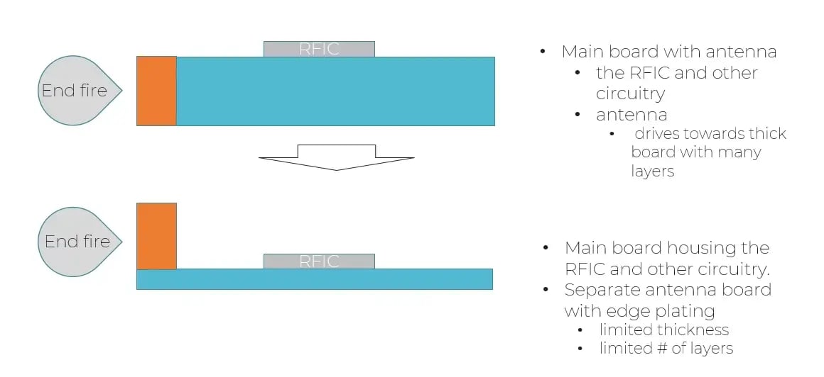
I had this idea - separate PCB for the antenna, that is somehow connected to a "main" device PCB and gives us end-fire radiation. Look at Fig.1, that pretty much summarizes it.
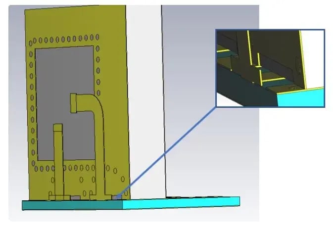
"Somehow connected to a device" is, unfortunately, not a sufficient description for working antenna topology, so together with my team, we came up with an edge-soldered transition. The antenna itself is a dual-polarized cavity, that provides a wide band and - due to around 2mm total thickness - is stable. Fig.2 shows the transition area and single antenna element.
For the first prototyping and measurement round, we decided to assemble it manually in our laboratory. Both, the main PCB and antenna PCB have soldering pads for future assembling.
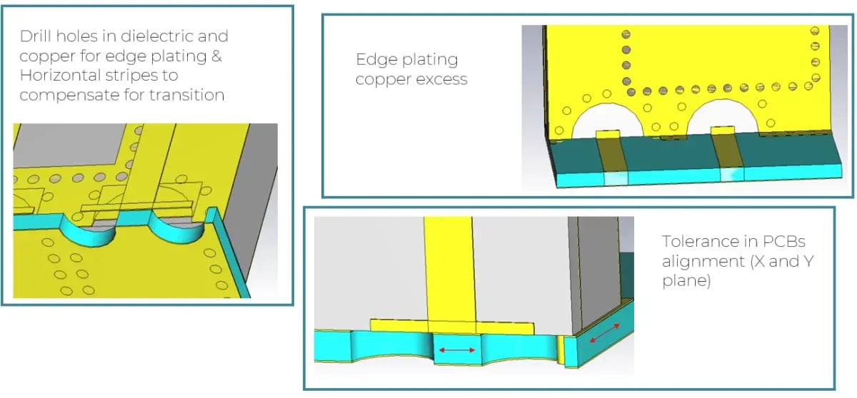
Turned out, it is quite hard to simulate everything that affects performance on mm-wave frequencies. Our edge-soldering approach didn't make the process easier. I have described some of the issues, that come with simulation and manufacturing in one of my previous blogs. Some of the things, that we took into account are featured in Fig.3
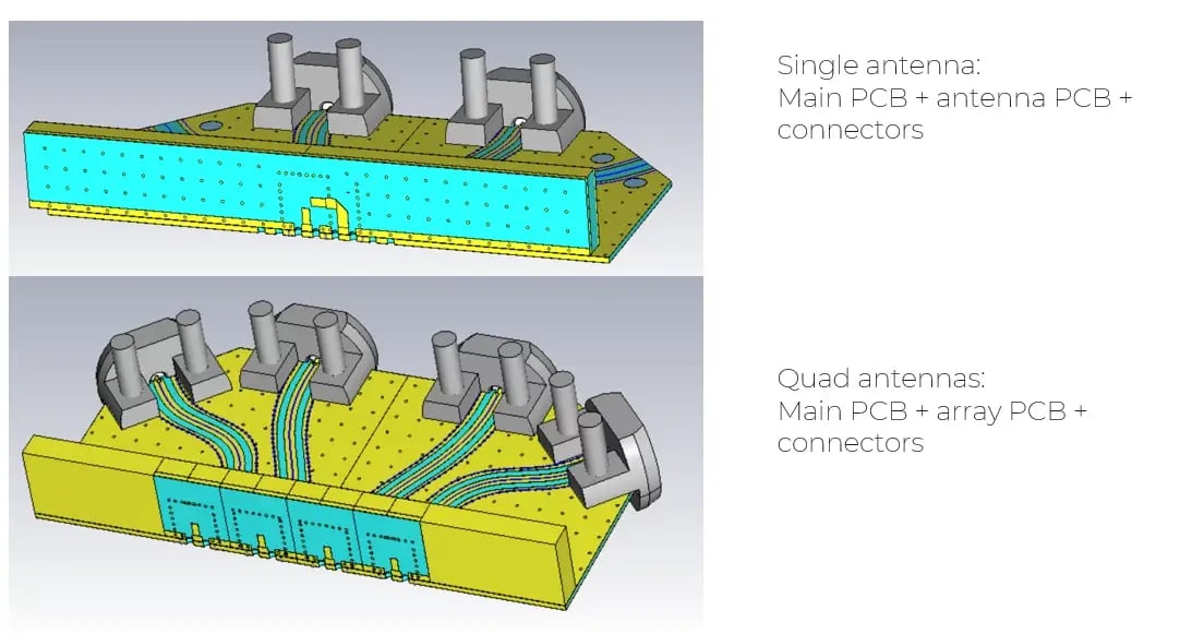
Finally, after many rounds of simulations, we came up with a ready-to-manufacture design (Fig. 4). One for a single element - to have some reference point. And one for antenna array - with single polarization for simplicity. We intentionally fed each element in the antenna array separately to measure them one by one and combine the results in post-processing.
In the end it all came together. Literally. I assembled prototypes in our laboratory and measured them in mm-wave anechoic chamber.
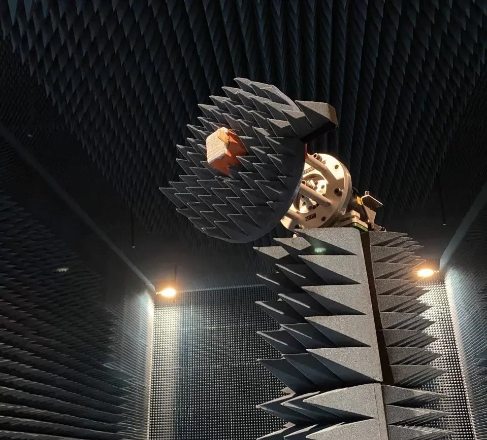
That tiny thingy in the middle of the rotating device in Fig.5 is the array. The total size of which is 5.85x23x1.9mm.
Measurements and post-processing take a lot of time. We have to be sure, that everything is allied perfectly and that no mistakes were made during the simulation or measurement phases. And if there is a mistake, we need to figure out where it came from and how to solve it. For example, figure 6 features gain pictures for a single corner element in the array.
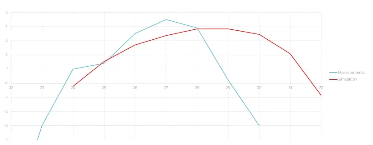
As you can see, measurements and simulation are allied pretty well until 28GHz but then measured gain has a drop, while simulated gain keeps a high level. That might be due to impedance inconsistency in the transition area on higher frequencies. Or not so stable connector, that started radiating on its own. The investigation is ongoing.
In general, the first round of prototyping was helpful and full of hidden challenges. The next stop is a dual-polarized array with beamforming. Stay tuned!
P.S. Video presentation from EMC2021 is HERE
This blog article was originally posted on the author's LinkedIn.
Disclaimer: The views and opinions expressed in this article are those of the author. It is intended only as a sharing of antenna design knowledge for educational purposes.